The Dilduino is the name for the brains of the Mod — the hardware and software that work together to get you off. Let’s take a look.
Hardware
The Dilduino is very similar to an Arduino Leonardo or Arduino LilyPad USB (or any other ATmega32u4-based Arduino). We’ve made three special additions for our version:
- Integrated motor driving circuitry — connect your 3 vibration motors at 1+/1-, 2+/2-, 3+/3- and each is directly connected to the battery.
- Integrated battery charging over USB.
- On-board multiplexer for selecting between inputs. The Hacker Port on your Mod gives you regulated 3.3V power (up to 350mA) and two pins for sensor/controller communication in a standard USB port. The multiplexer acts as a switch to give you two PWM outputs, I2C/Two-Wire sensor communication, analog sensor communication and software serial communication, all on the same pins.
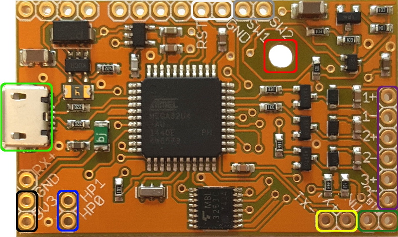
Dilduino Front

| Color | Function |
|---|---|
| Micro B USB port for charging/programming | |
| 3.3V output (350mA max) for peripherals | |
| Hacker Port access for I2C (HP0=2,HP1=3)/software serial (HP0=15//RX,HP1=14//TX)/analog in (HP0=A7,HP1=A9)/PWM out(HP0=D6,HP1=D9) | |
| #4 / 3mm mounting hole | |
| Serial transmit status LED | |
| External active-low button hookup | |
| Connections for 3 vibration motors | |
| Momentary button on/off switch | |
| Reset button |
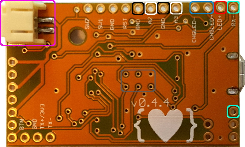
Dilduino Back

| Color | Function |
|---|---|
| JST connection for single-cell Li-polymer battery | |
| SPI interface | |
| Serial receive status LED | |
| User LED (13) | |
| Battery charge status LED | |
| Analog inputs | |
| Ground |
Software
We have two important pieces of software for using your Mod. The first our open-source OSSex software. It’s an Arduino library that sets up all of the various inputs and outputs and has functions for storing and running vibration patterns. Release milestones are available at GitHub.
The second is the sketch loaded on your Mod, Mod Sketch. It uses OSSex to provide the patterns that come shipped with your Mod, sets the button behavior (click moves to next pattern, double-click increases intensity, etc.), creates a serial console and has the startup sequence that blips all 3 motors and flashes the LED. If you want to change how your Mod runs, this is a good place to start. Release milestones available at GitHub.
Want to get started programming your Mod? We have a how-to to guide you through the basics.
Serial console
The Mod Sketch creates a serial console that you can use to interact with or tweak your Mod without having to upload new code. Simply connect to it with a serial terminal app (such as the one built-in to the Arduino IDE, or HyperTerminal or zterm, etc.) at 9600 baud and start typing away. Below is a run-down of the commands it accepts:
l,xto set the LED
To set the LED to a power of 200:
l,200
To turn the LED off:
l,0
0,x,1,x,2,x,-1,x,… to set a particular output (motor)
To turn all outputs on to 150:
-1,150
To turn output 2 to 220:
2,220
cto cycle through the patterns. This will return the current pattern number.gto get the current pattern number.sto stop all patterns and turn all outputs off.r,xto run a particular pattern.
Run the first pattern:
r,0
You can adjust power and time settings with p,P,t, and T. All power and time adjustment commands will return the current power or time scale, with 1.0 being normal. A power scale of 1.5 means all patterns will run at 50% higher power than normal. A time scale of 0.75 means that all patterns will run 25% faster than normal.
pto decrease power.Pto increase power.tto decrease pattern step time (run faster).Tto increase pattern step time.
Read an input:
i,0
The i command reads a given input channel on your Mod and prints that value to the console. Mods have two inputs, so i,0 and i,1 are the two options for now.
Peter Fox
Hi, I was wandering if you guys have an example of adding a bluetooth module to the main board?
Also do you have any graphs on how long the battery lasts off one charge?
Comingle
Hi Peter — the bluetooth module would have to be one which supports I2C slave mode, which many do (such as this one: http://media.digikey.com/pdf/Data%20Sheets/BlueGiga%20PDFs/BLE113.pdf). It’s something that we hope to offer as an easy plugin accessory.
We don’t have graphs about battery life because it’s just very much going to depend on usage (and the type of battery you have connected, if you’re running your own Dilduino board). To give some perspective though, we’re using 875mAh batteries in the Mod and the motors that we’re using draw about 250-300mA at full power. Power draw from the microcontroller is negligible in comparison, so we would expect the Mod to last roughly an hour with all 3 motors running at full bore.
This is not necessarily the type of usage that is common though — running all 3 motors at max power is a pretty intense session.
We have regularly have several hours of use from the Mod before it needs charging. There is also the issue of external devices: you can draw power through the hacker port, and that is going to influence battery life as well.
Billy Kirkpatrick
Is it possible to ‘brick’ the Mod. I recently received my device and uploaded a custom sketch from the Chrome plugin. Now I am unable to turn on the device. Please help!
Comingle
Hi Billy — we have never found a way to brick the Mod but it’s definitely possible to upload code to it that doesn’t work.
The basic way to fix it is press the reset button twice on your Mod and the LED will start flashing. At this point you can upload a new sketch to the toy. The LED will only flash for 8 seconds, however, you it might require a bit of timing to get it right.
If you wish to do this from the Modify app, there is an option for “My toy isn’t here” in the dropdown where you select what port your toy is connected to. From there, it will take you to a Restore page that will have instructions on getting your Mod back to a plain state.